GSX-R Clock Conversion
GSX-R Clock Conversion
All information supplied with
thanks to Rick Haliday
Rickhaliday@xtra.co.nz
For those of you who do not /cannot build your own electronics for this I suggest you contact Mark at e-repair.org
Mark, is the guy who looks after all my electronic repairs including my computer monitors when they decided to die over the last 10 years or so.Re hashed my setup and proved you can do the
same thing with readily obtainable equipment. Not my home built electronics. Geo of KGB drew the circuit diagram in Tiny Cad V1.6 TinyCad home page for the latest version of this VERY useful FREE Program.
RG to GSXR conversion colours (Refer to RG Console.jpg)
Basically what you’ll need are the following. I have change some components from my
original setup to prove any one can build it
A GSXR 600/750/1000 Instrument console from a 2001 upwards. (I got this and the harness
off EBay)
Hint if you get a
Australasian version.
An Instrument/headlight harness from a GSXR 600 .You could make your own but I like
shortcuts and just needed to
re-end the connectors to mate to the standard wiring harness.
GSXR Speedo Pickup Part No 34990-33E10 ( Think these part numbers are right but I’ve
thrown away the original wrappers)
GSXR Speedo rotor Part No 34981-35F00
Smart Com CDI type Tach Interface 010113P1-01 obtainable from http://www.vtac.co.uk/
Daytona Water Temperature Gauge obtained from Cal Sports http://www.calsportbike.com/
Car noise filter Part no AA3072 obtained from www.jaycar.com.au ( Any Car audio supplier should
have an equivalent. I have found this necessary to get a good tach reading )
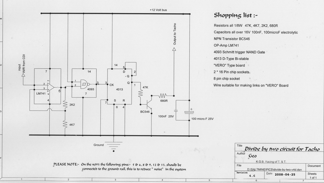
Also a simple divide by two circuit. I built mine using a 4093 NAND gate Schmitt trigger
feeding a 4013 Dual D Edge triggered Flip Flop with its output to a BC 546 transistor
There is a very active Yahoo user group as well !!
TinyCad Yahoo Group
For best results please set your printer for LANDSCAPE MODE when asked to confirm printing of Circuit Diagram
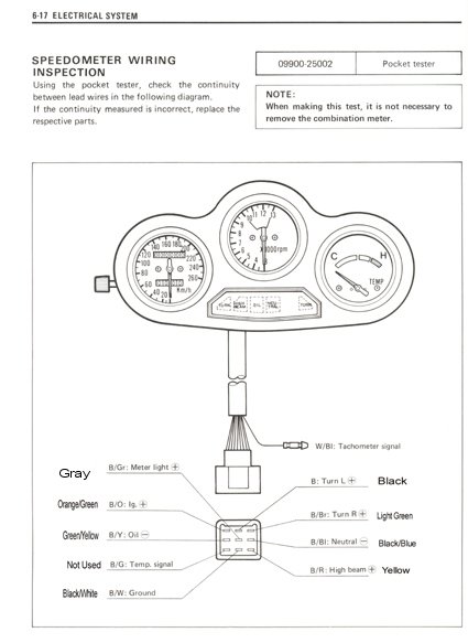
B/Gr
Grey
B/O Orange/Green
B/Y Green/Yellow
B/G Not Used
B/W Black/White
B Black
B/Br Light Green
B/Bl Black/Blue
B/R Yellow
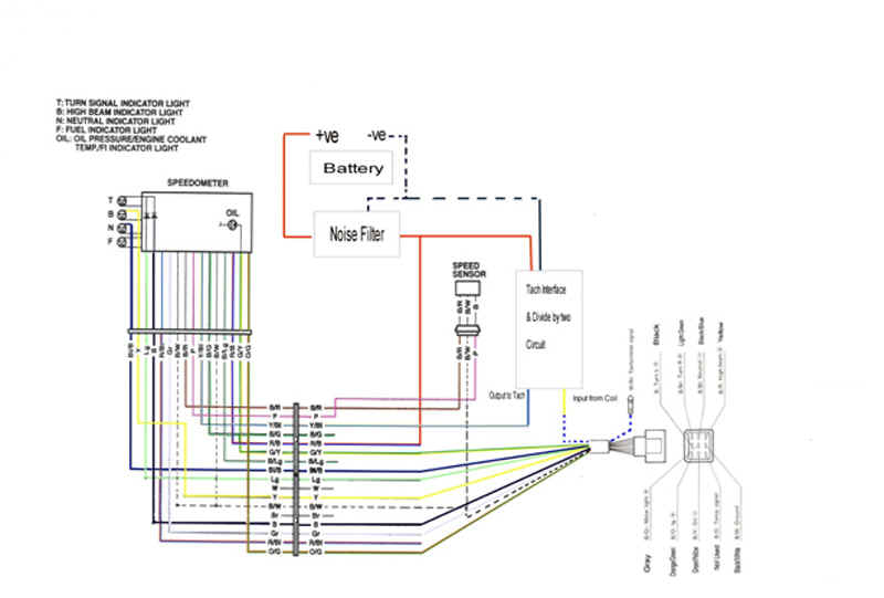
Other connections needed for new console.
Red/Blue Must be connected to a always on +12v ( E.G. Red to ignition switch)
Black/Red to Speedo Sensor
Pink to Speedo Sensor
Yellow/Blue to output of Divide by two circuit
Tach Interface connections:
The Yellow wire is connected to the White/Blue wire (tach signal)
The Red wire is connected to the output of the noise filter (for a clean signal)
The Black wire is connected to ground (Any Black/White wire)
The Blue wire is connected to the divide by two circuit input
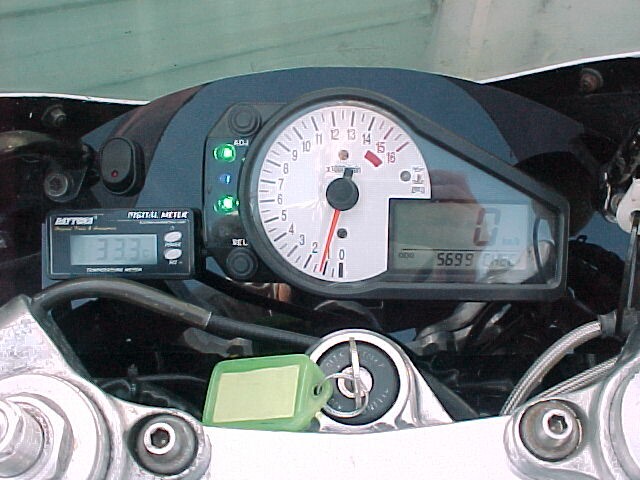
When finished all indication light are there as well as an oil low light and warning
symbol on the LCD.
Black / Green
Black / Light Green
White
Red / Black